Logix Features

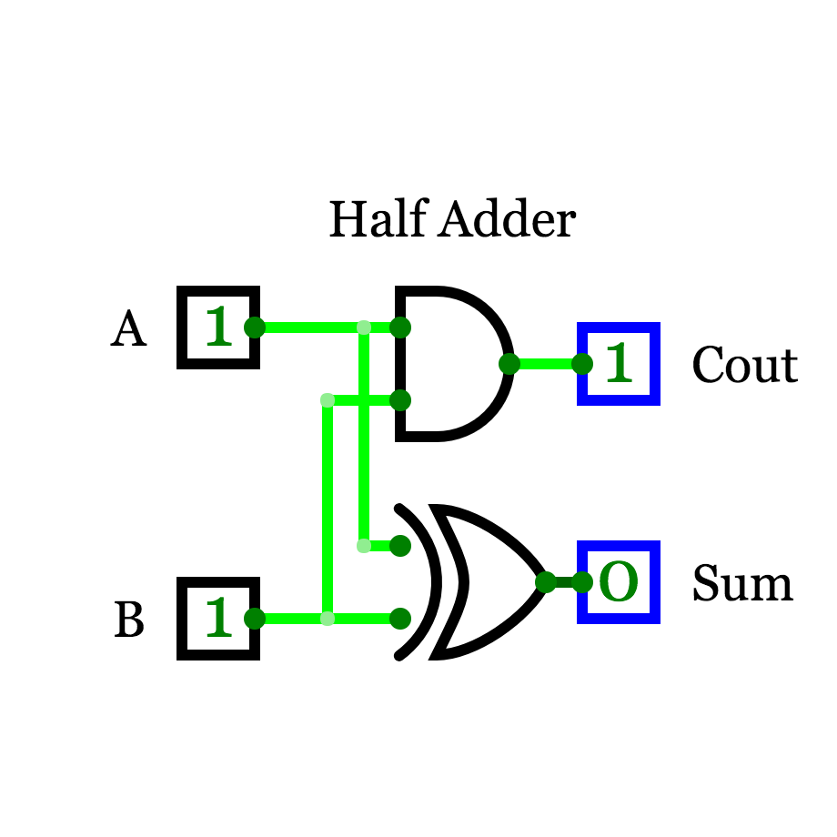
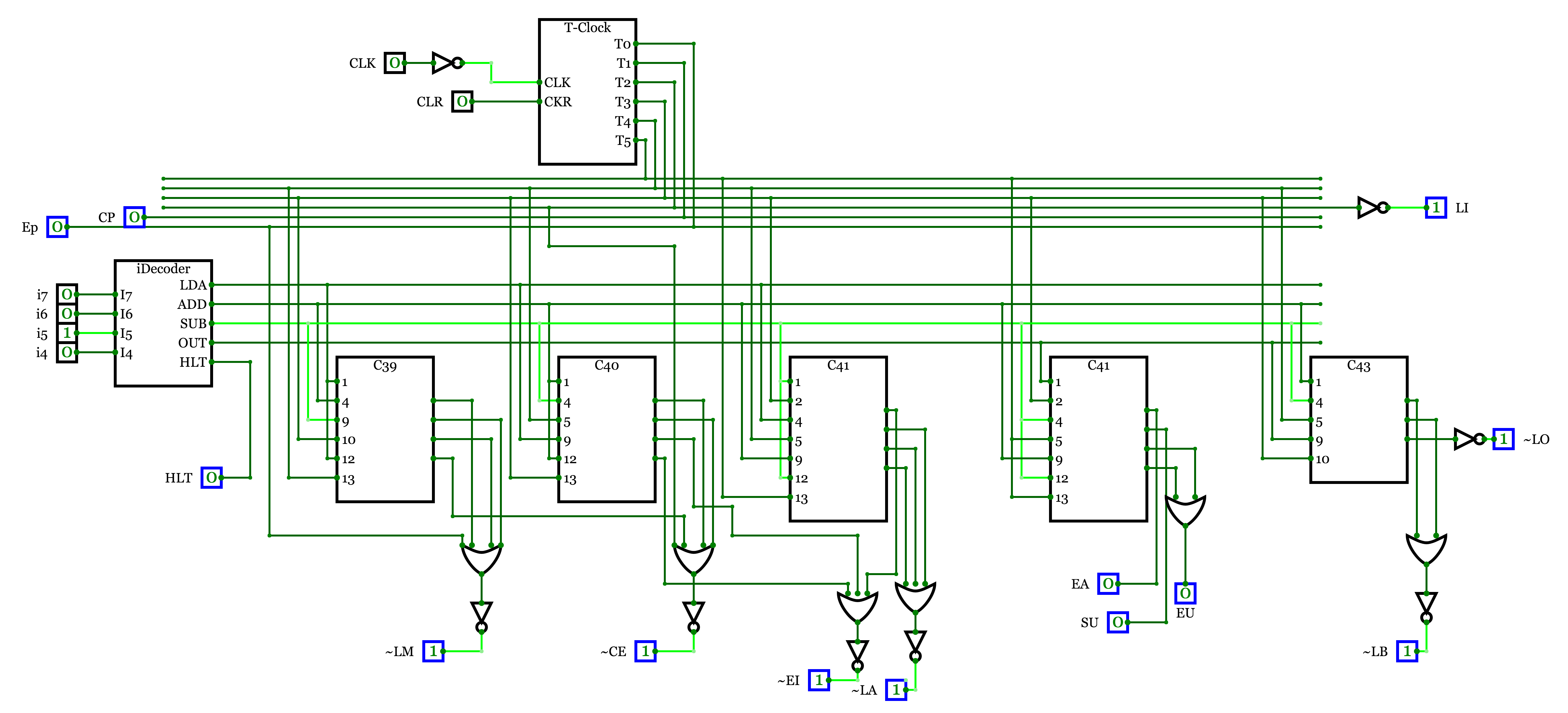
Design circuits quickly and easily with a modern and intuitive user interface with drag-and-drop, copy/paste, zoom and more. The main features have been listed below.

THIS IS AN ALPHA TEST RELEASE. PLEASE AVOID DISTRIBUTING OR SHARING IN PUBLIC CIRCLES. Mainly released for testing within IIIT-Bangalore.
Responsive image

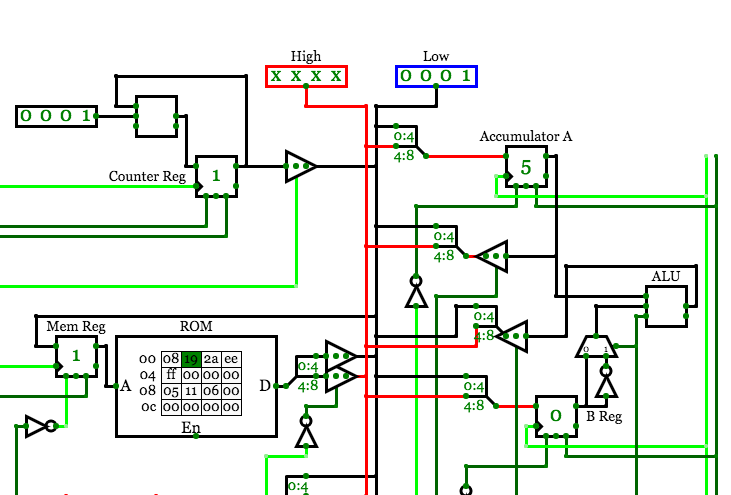
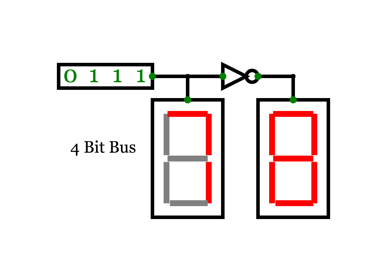
Multi Bit Buses and components

Logix supports multi bit wires, this means circuit design is easier, faster and uncluttered. To change the bitWidth of the circuit elements, Just select the circuit element and change the bitwidth value in the property menu.

Responsive image

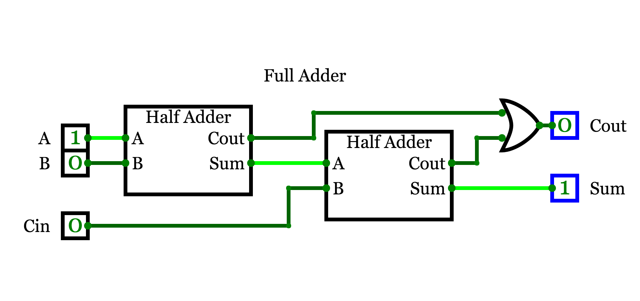
Sub circuits

Create subcircuits once and use them repeatedly. This allows easier and more structured design. Future versions will allow importing of subcircuits from external sources. To use a subcircuit, simply create and design the subcircuit as a normal circuit and Label inputs and outputs. Then after that create another circuit within the same project and click circuit -> insert subcircuit and select the subcircuit.

Responsive image
Responsive image

Export High-Resolution Images

Logix can export high resolution images in multiple formats including SVG.

Responsive image

Combinational Analysis

Automatically generate circuit based on truth table data. This is great to create complex logic circuits and can be easily be made into a subcircuit.


Plotting and Debugger

This feature is still under development. This will allow the user to set debug flags to see the Time Plot. The Debugger will allow the user to find logical mistakes in the design.


Embed in PowerPoint and Blogs

Since Logix is built in HTML5, an iFrame can be generated for each project allowing the user to embed it almost anywhere.